Rfid door locks and rfid attendance system are very popular now days and many hotels provide provide rfid tag to their customer to lock and unlock the door.
Rfid door lock block diagram.
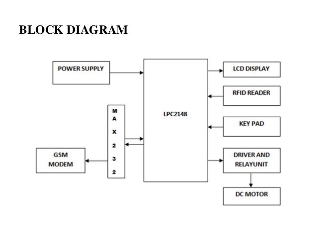
Figure 5 shows the access control system block diagram using arduino and rfid.
This system prevents a large destruction and loss the project is based on rfid rc522 module.
How rfid works and how to make an arduino based rfid door lock howtomechatronics retrieved 15 october.
Any rfid system will consist of a rfid reader and a rfid tag.
It provides serial.
The tag will often be small and portable with little to no electronics in it.
Block diagram of door security system using rfid rc522.
Level 1 block diagram 10.
Automatic door lock system circuit diagram.
Don t know about rfid rc522 module i will explain later.
The rfid reader is placed on the outside of the door and it is detached from the controller confidentially so no one can avoid the security by breaking open the rfid reader and trying to short circuit the reader.
Em 18 rfid reader operates at 125 khz and it comes with an on chip antenna and it can be powered with 5v power supply.
It will contain a rfid reader writer and a magnetic door lock for simple use.
Tcp ip 4 door entry access control panel kit electric strike fail secure no mode lock enroll rfid usb reader 110 240v power supply box rfid reader phone app remotely open door 4 9 out of 5 stars 71 319 99 319.
Lcd is used to display messages.
The goal is to open a door by using a specific tag that functions as an access badge.
Servo motor is used to indicate that the door is opening or closing.
Each rfid card has a unique id embedded in it and a rfid reader is used to read the rfid card no.
If the wrong tag is scanned the door will stay closed and set off a buzzer.
Arduino uno is the brain of this project.
Arduino rfid door lock circuit diagram.
We ll start with explaining the underlying tech before walking through a tutorial of how you armed with little more than an arduino and some rfid tags and a sensor can implement your own door.
This project guide will detail the steps to create an rfid radio frequency identification door lock system using an arduino mega 2560.
Rfid stands for radio frequency identification.